Light Bulb Schematic Symbol Wiring Diagram Schemas
A solenoid valve is an electromechanically operated valve . Solenoid valves differ in the characteristics of the electric current they use, the strength of the magnetic field they generate, the mechanism they use to regulate the fluid, and the type and characteristics of fluid they control.

solenoid valve symbology Meaning of solenoid valve graphic symbol
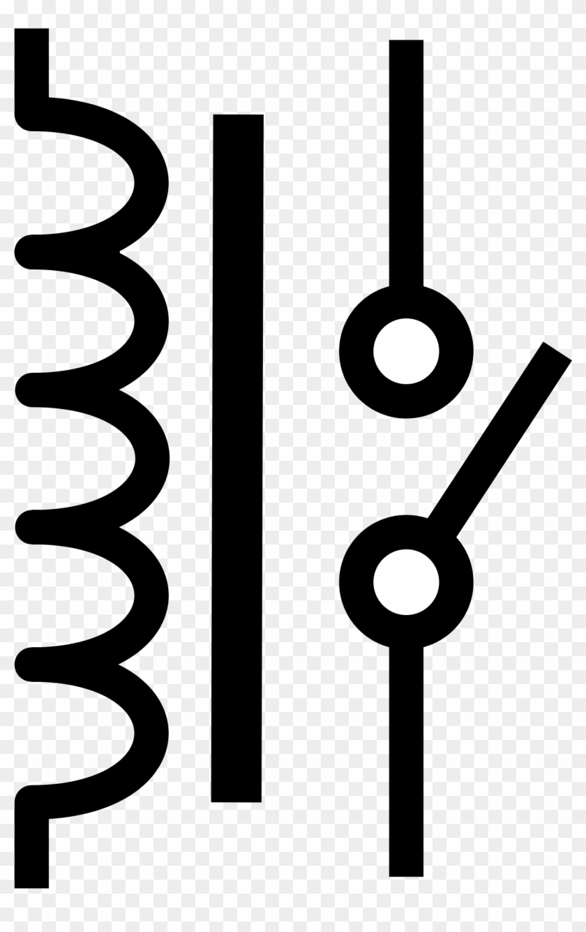
Standard electrical IEC symbols also known as IEC 60617 (British Standard BS 3939) used to represent various devices including pilot lights, relays, timers and switches for usage in electrical schematic diagrams. Solenoid. Category: Solenoid Valves. Stencil: IEC Symbols. Tags: solenoid valves, solenoid. Edit. SVG PNG JPG DXF DWG. Solenoid.

Solenoid Schematic Symbol
Solenoid Symbol in Electrical Schematic. In electrical schematics, a solenoid is represented by a specific symbol that indicates its function and operation. The solenoid symbol is commonly used to represent a device that converts electrical energy into linear motion. It is widely used in various applications, including control systems.
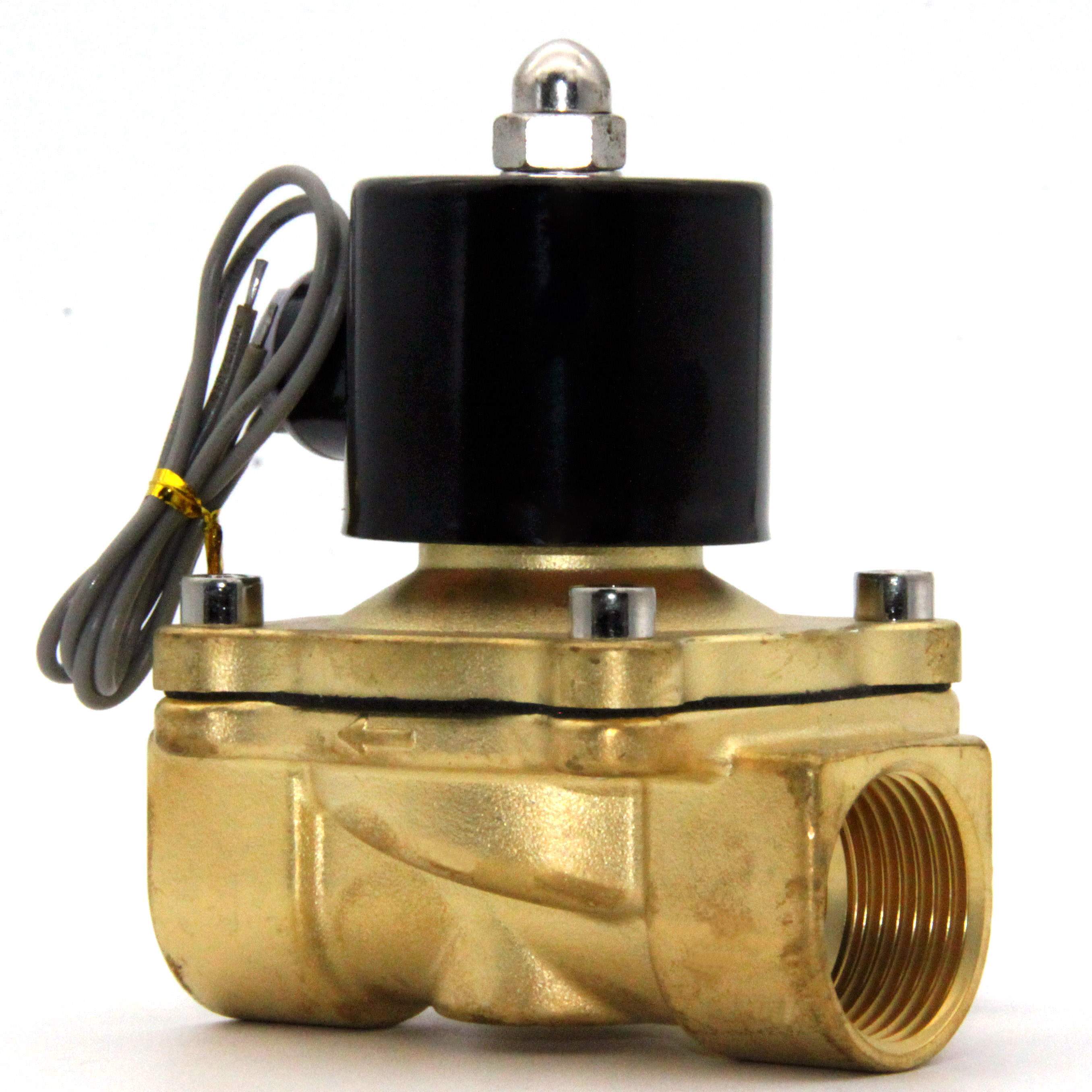
solenoid valve 24vdc 1.00 npt Solenoid npt 24vdc
This chapter of hydraulic symbology covers most of what needs to be known to read and create the average hydraulic schematic, since actual electrical symbols are somewhat different. Starting with Figure 1, there are three ways to draw an electric operator for solenoid valves, which most people recognize. The first operator is the symbol for a.

solenoid valve symbol schematic Valve symbols solenoid schematic drawing actuators pneumatic
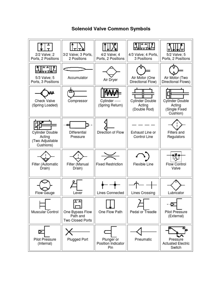
Solenoid valve symbols 1. Solenoid valve symbols in fluid power diagrams Fluid power drawings are crafted up by engineers to understand and analyze power units. These diagrams have standard-based graphic symbols representing the complete operation and direction of fluid flow within a power unit. Figure 2: A 2/2 valve symbol
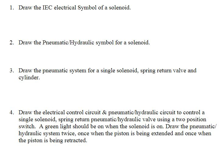
Solved 1. Draw the IEC electrical Symbol of a solenoid. 2.
Potentiometer Solenoid Valve Normally open Contact (N/O) Normally Closed Contact (N/C) Change Over or 2 way Contact Made position Fused Switch Open Contact (N/O). This is not a definitive list of all symbols used in electrical identification, but merely a guide to some of the more commonly used symbols. Due to the number of variants

solenoid valve symbol cad 3 2 solenoid valve circuit diagram
The spring symbol defines the "at Rest" position of the solenoid valve. The spring "pushes" from the side it is drawn on and places the right side block diagram of the valve in function. The T Symbol. This symbol indicates that a port is closed and is neither passing or exhausting gas. Pressure of air supply symbol.
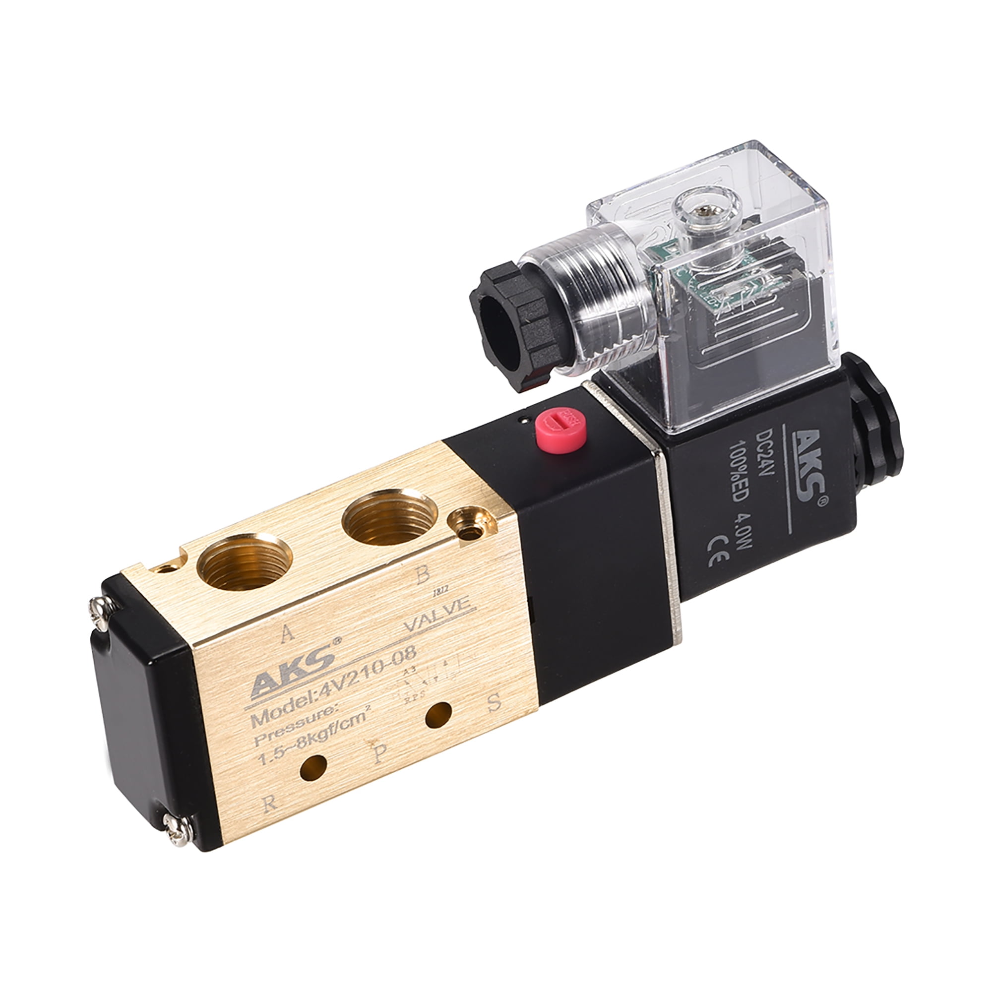
4V21008 Air Single Electrical Solenoid Valve DC24V 5Way 2Position 1/4" PT Internally Piloted
sinθ = y y2 +R2− −−−−−√. (12.7.3) Figure 12.7.1: (a) A solenoid is a long wire wound in the shape of a helix. (b) The magnetic field at the point P on the axis of the solenoid is the net field due to all of the current loops. Taking the differential of both sides of this equation, we obtain.

3/2 solenoid valve symbol Solenoid valve air smc electric symbol 24v position 3way series dc12v
Electrical symbols and electronic circuit symbols are used for drawing schematic diagram. The symbols represent electrical and electronic components. Table of Electrical Symbols See also Electrical components Electrical units Capacitor Resistor Inductor Current Voltage Ohm's law Switch symbols Ground symbols Resistor symbols Capacitor symbols
solenoid valve symbols explained Solenoid valves descriptive regrettably nearly
Generic Fixed Inductor This is the symbols used for representing a generic Inductor whose inductance value is fixed. An inductor is also known by many names such as coil , choke etc. stores energy inside magnetic field. Variable Inductor This type of inductor has variable inductance.

Wiring Diagram Symbols Connector Doctor Heck
Relay Symbols and Electromagnets. The relay are switching electrical devices activated by signals. Most of the time, a small voltage or current is used to switch other voltages or higher currents that may be electromechanical or fully electronic type. The electromagnetic controls are activated thanks to electromagnetic fields generated by.
Circuit, diagram, electric, electronic, solenoid operated relay icon Download on Iconfinder
A solenoid allows us to magnetize wires, creating a magnetic field, and then demagnetize them whenever we like (pretty much). All with the push of a button. Or the twist of a key. Like we said before, cars use solenoids. Turning the ignition key relays electrical energy from your battery into a starter solenoid.
Circuit, diagram, electric, electric valve, electronic, relay, solenoid valve icon Download on
A solenoid ( / ˈsoʊlənɔɪd / [1]) is a type of electromagnet formed by a helical coil of wire whose length is substantially greater than its diameter, [2] which generates a controlled magnetic field. The coil can produce a uniform magnetic field in a volume of space when an electric current is passed through it.

Solenoid Wiring Diagram Symbol Easy Wiring
The first shows the number of ports, the second shows the number of valve positions. The symbol for the solenoid or the pressure-operated valve has the same number of squares as the valve has positions. The right-hand square shows the valve in its non-actuated (rest) position, the left-hand square corresponds to a valve in its actuated (work.

Basic Electrical and Electronic Symbols Electrical Technology Electrical Circuit Symbols
Location Symbols for Installations Popular Symbols Making and breaking current Isolating Making, breaking and isolating Lamps & Lighting The following table provides the commonly used electrical wiring schematic symbols for push-buttons and lamps which comply with the IEC and BS Electrical Symbols.
Solenoid Icon Black Stock Illustration Download Image Now iStock
A solenoid is a device comprised of a coil of wire, the housing and a moveable plunger (armature). When an electrical current is introduced, a magnetic field forms around the coil which draws the plunger in. More simply, a solenoid converts electrical energy into mechanical work. The coil is made of many turns of tightly wound copper wire.
